This chapter outlines the methods of calculation used by HighRoad and describes some limits you need to be aware of.
![]()
The triangulation is constructed using the properties of a Voronoi diagram. A voronoi diagram consists of a set of polygons one for each point. The space enclosed by the polygon for a point is such that anywhere within the polygon is closer to point P than any other point. (Refer to Figure 24-1.)
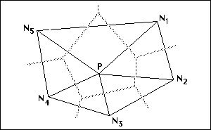
Each edge is associated with a link from point P to one of its neighbours N and the edge of the polygon is a perpendicular bisector of the link to the neighbour N. The triangulation is the set of all links corresponding to an edge on a voronoi polygon. You should verify that this correctly models the shape of the terrain particularly that no triangle edges cross linear features such as ridges, gullies, drainage ditches, kerb lines etc. If necessary you may have to insert a feature string as a breakline to correct the triangulation.
![]()
Method of calculating quantities
The volume of earthworks is calculated using the mean end area method. The area of cut and fill at each section at the nominated interval is calculated to the nearest square centimetre. The volume of cut (and fill) between two consecutive surveyed sections is calculated as the sum of the cut areas of the two sections multiplied by half the distance between the sections. The volume is calculated to the nearest 0.001 cubic metre.
Calculation of earthworks after stripping
Figure 24-2 shows the method used to allow for stripping before calculating quantities. The finished surface of the cut batter intersects with the natural surface. The natural surface is lowered by the depth of stripping between the points where the batter intersects the natural surface. The cut and fill volumes are then calculated.
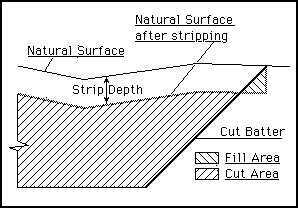
You can see that in the case of a cross section which is totally in cut, a very small quantity of fill will be calculated in the area below the cut batter and down to the stripped surface. The cut batter is shown with no surface treatment in Figure 24-2. In cases where there is a layer of topsoil on the cut batters, the earthworks would be calculated to the underside of the topsoil layer. If the depth of topsoil on the batter is equal to greater than the depth of stripping, the section would be totally in cut.
Allowance for surface layer thickness
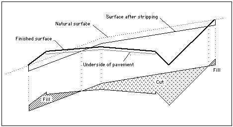
When calculating quantities, HighRoad allows for the thickness of the surface layers. The cut and fill volumes are calculated between the underside of the surface layers and the natural surface stripped of topsoil. This is shown in Figure 24-3.
Allowance for bulking or compaction
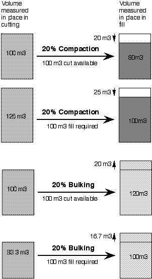
Consider the case where the volume of earth from a cutting occupies less volume after it is placed and compacted in a fill. If 100 m3 of earth from the cutting (measured in place) occupies 80 m3 when it is compacted into a fill (again measured in place), this would be specified as 20% compaction. The volume changes by a factor of 0.8 from cut to fill.
When calculating cut to fill, HighRoad takes into account compaction or bulking. Continuing with this example, that is, a compaction factor of 0.8, if the road had a cut volume of 100 m3 and a fill volume of 80 m3, this would be listed as:
100 m3 of cut to fill.
There would be no cut to spoil or borrow to fill, that is no excess cut to dispose of, or excess fill to bring onto the job.
If there was 100 m3 of fill required in this road, HighRoad calculates the amount of cut required for this fill by dividing the volume of fill by the compaction factor. In this case, the volume of cut (measured in place) required for a 100 m3 fill is:
100/0.8 = 125 m3.
As there is only 100 m3 of cut available, an additional 25 m3 would be required. This would be listed as:
100 m3 cut to fill
25 m3 borrow to fill.
Note: These calculations make no allowance for the volume occupied by the earth during transport. The volume occupied by 100 m3 of earth from cutting may increase by 30% when it is loose while being hauled. If you wish to estimate the loose volume for haulage you must take account of this separately.
Figure 24-4 shows diagrams of 20% compaction and 20% bulking for the case where 100 m3 of cut is available and 100 m3 of fill is required.
![]() Maximum distance between
offsets
Maximum distance between
offsets
The maximum distance allowed between consecutive offsets on a cross section is 1000 m. The maximum difference between consecutive elevations is 100 m. There is currently no range checking in place to ensure that these criteria are met. If your design exceeds these values, errors in the calculation of earthworks volumes and in the drawing of cross sections may occur.
Maximum length of road
The maximum length of road that can be designed is 32 km. (This length is controlled by the maximum value of the horizontal scroll bar.)